Overview
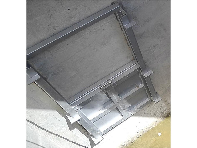
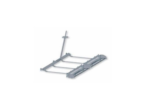
The pneumatic flap valve is used to control and discharge the backwash wastewater from the filter pool. The flap valve consists of a valve plate, valve frame, valve shaft, push-pull rod, gear rod, bracket, and pneumatic drive device, among others. The valve plate is installed on the inner wall of the filter pool, and the push-pull rod connected to the valve plate passes through the drainage channel. The pneumatic flap valve is a complete set of equipment, providing a pneumatic actuator and all necessary accessories for normal operation, such as bolts, nuts, and all fasteners. Each set of equipment includes all the accessories needed for normal operation to ensure the system operates safely, effectively, and reliably.
Working Principle
The flap valve has high strength, is easy to install, use, and maintain, and closes tightly, with the leakage rate strictly controlled within the required limits. It relies on chemical bolts and rapid concrete curing. No embedded parts are needed, and the valve plate can be easily installed to rotate around the bottom pivot or rotate the rubber for a 90° rotation to control the liquid level. When the valve is closed, it seals on all four sides; when opened, three sides remain sealed except for the top, to control the liquid level and prevent filter material loss.
Main Technical Indicators
| Main Components | Material |
| Valve Body | Stainless Steel |
| Valve Frame | Stainless Steel |
| Sealing Rubber | EPDM |
| Connecting Rod | Stainless Steel |
| Crank | Stainless Steel |
| Push Rod | Stainless Steel |
| Bearing | Stainless Steel |
Structural Features
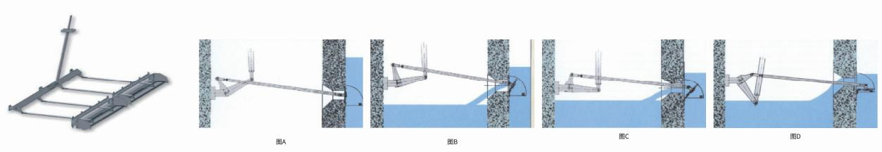
The flap valve is driven by the actuator, which is selected in a pneumatic form.
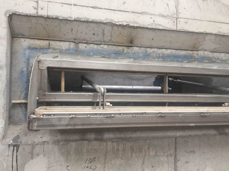
When the push rod is at the upper stop point, the flap valve body and frame are sealed, and the actuator stops operating (as shown in Figure A). At this point, the backwash process of the filter pool begins, and water flushes out impurities and waste from the filter material.
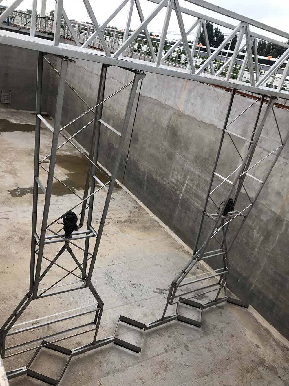
When the actuator is opened, the push rod will press down, pushing the crank to move in an arc around the crankshaft, driving the connecting rod to open the flap valve (as shown in Figures B and C), causing suspended impurities in the filter pool to overflow.
When the push rod is at the lower stop point, the flap valve is fully open, and impurities in the filter pool overflow with water, achieving the effect of discharging sewage (as shown in Figure D).
The actuator pulls the push rod back up from the lower stop point, closing the flap valve again, restoring its original state, and achieving the function of restoring the filtering capacity of the filter material.